Description of Sun Tracking Solar Panel

Components in the Circuit:

  • Solar panel
  • ATmega8 micro controller
  • Light Dependent Resistor.
  • Motor driver IC
  • Stepper Motor.

Circuit-Diagram-of-Sun-Tracking-Solar-Panel-768x320

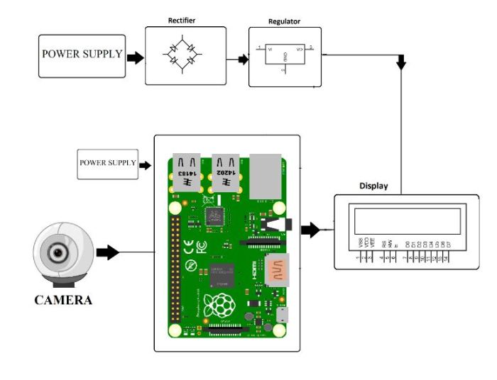
Automated Sun Tracking Solar Panel Circuit Design:

The proposed system consists of ATmega8 micro controller, Solar panel, Light Dependent resistors and motor driver IC.

ATmega8 is AVR family micro controller. It is based on advanced RISC architecture. It is an 8 bit controller. It has 4KB Flash memory, 512 bytes of EEPROM and 1Kb of SRAM. It has 23 programmable pins. It supports peripheral features like two 8-bit timers, one 16 bit timer, 6 channel ADC with 10-bit resolution, programmable USART, Serial peripheral interface, 2 wire serial interface, etc.

Solar panel is connected to Stepper motor. Solar panel consists of photovoltaic cells arranged in an order. Photovoltaic cell is nothing but a solar cell. Photo resembles light and voltaic is electricity. Solar cell is made up of semiconductor material silicon. When a light ray from Sun is incident on the solar cell, some amount of energy is absorbed by this material. The absorbed energy is enough for the electrons to jump from one orbit to other inside the atom. Cells have one or more electric field that directs the electrons which creates current. By placing metal contact energy can be obtained from these cells.

Light Dependent Resistors are the resistors whose resistance values depend on intensity of the light. As the intensity of light falling on the LDR increases, resistance value decreases. In dark, LDR will have maximum resistance. LDR will output an analog value which should be converted to digital. This can be done using analog to digital converter. ATmega8 has analog to digital converter internally. It has six ADC channels from ADC0 to ADC5.The two LDRs are connected to ADC pins i.e. PC0 and PC1. ADC conversion is done using successive approximation method.

Stepper motor rotates the panel in a stepwise angle. To drive this motor a driver IC is used. Driver IC amplifies the input voltage and protects the microcontroller from back EMF. Generally, motors generate back EMF. This may damage the controller. The driver IC used is L293D. It has H bridge internally made up of transistors. This IC has 16 pins. Output pins are connected to the stepper motor pins. Input pins are connected to the controller pins as shown in circuit diagram.

By connecting a battery to the solar panel, one can store the energy generated by the solar cells and this energy can be used when required.

Sun Tracking Solar Panel

Two light dependent resistors are arranged on the edges of the solar panel. Light dependent resistors produce low resistance when light falls on them. The stepper motor connected to the panel rotates the panel in the direction of Sun. Panel is arranged in such a way that light on two LDRs is compared and panel is rotated towards LDR which have high intensity i.e. low resistance compared to other. Stepper motor rotates the panel at certain angle.

When the intensity of the light falling on right LDR is more, panel slowly moves towards right and if intensity on the left LDR is more, panel slowly moves towards left. In the noon time, Sun is ahead and intensity of light on both the panels is same. In such cases, panel is constant and there is no rotation.

Description of Sun Tracking Solar Panel

Streaming Videos using Webcam

Raspberry Pi can be used as a webcam server where we can live stream video over a local network using python scripts and some required packages. A software package used in this project is Motion which is an open source software with a number of configuration options which can be changed according to our needs. Here configurations are to be made so that it allows you to create a remote webcam for your Raspberry Pi so that you can view it from any computer on the local network.

raspberry pi streaming.jpg

Prerequisites & Equipment:

  1. A Raspberry Pi Model B or greater.

  2. A USB WiFi Adapter (Edimax – Wireless 802.11b/g/n nano USB adapter is used here).

  3. A USB webcam with microphone / USB microphone (Logitech USB Webcam is used here).

  4. An SD Card flashed with the Raspbian OS.

  5. Access to the Raspberry either via a keyboard and a monitor or remotely.

Descritption of LCD scrolling display Module

The project is discussed in two parts.

Part 1: To Create LCD module:

In part one LCD module is created using AVR controller and 16×2 alphanumeric LCD display. The controller ATMEGA16 controls the LCD. The programmed code dumped permanently to this atmega16 is controlling the LCD module. A single receiving pin (RXD -14) of ATMEGA16 is the only input of this LCD module. The data received by serial communication is displayed on the LCD module in a scrolling manner.

Part2: Interfacing the LCD module using any other microcontroller:
In part two the controller used is in our project is another AVR chip. The data send to the LCD module via serial transmission pin (TXD-15).A switch demonstrated in our project give the input to the controller.A predefined text is transmitted to the LCD module upon every press of the switch. Whatever the text sends, the data will be scrolled in the LCD module.
Circuit Diagram:
avr_lcd_board.gif

LCD Scrolling Display Module

A microcontroller is a device which has an inbuilt processor surrounded by few dedicated hardware modules. Once the microcontroller initializes them they start operating on their own. In case of an ADC it will do the sampling and digital to analog conversion all by itself and keep the converted data in its buffer so that the microcontroller can read that later. The advantage of this kind of implementation is that the microcontroller is free to do other tasks during that time and hence increase the overall efficiency. That was the case of hardware modules or peripherals inside a microcontroller which increases the processing efficiency of the built in processor. The efficiency can increase even more if the external hardware attached to the microcontroller can also does lot more tasks by their own without depending the microcontroller. The hardware may or may not contain another processor so that it can perform certain predetermined task after initialized by the microcontroller.
An example for such a device is the serial LCD scrolling display. Once the data to be displayed in scrolling manner is received from the microcontroller, it will start the operation by its own and perform the scrolling process. This project explains interfacing of LCD MODULE with any type of controller using single serial receiving pin. In this mode only one pin is used for sending data. This scrolling display mode has the advantage over the 8-bit mode as it uses only a single pin. The remaining pins of the controller are available for normal use and the valuable processing power required to scroll the data can be used for any other purpose.
avr_lcd_board_1.jpg

Raspberry Pi Vehicle Number Plate Recognition

Recognizing vehicle number plates is a difficult but much needed system. This is very useful for automating toll booths, automated signal breakers identification and finding out traffic rule breakers.
Here we propose a Raspberry Pi based vehicle number plate recognition system that automatically recognizes vehicle number plates using image processing. The system uses a camera along with LCD display circuit interfaced to a Raspberry pi. The system constantly processes incoming camera footage to detect any trace of number plates. On sensing a number plate in front of the camera, it processes the camera input, extracts the number plate part from the image. Processes the extracted image using OCR and extracts the number plate number from it. The system then displays the extracted number on an LCD display. Thus we put forward a fully functional vehicle number plate recognition system using Raspberry Pi.

Description of Raspberry Pi Based Vehicle Number Plate Recognition

Ultrasonic Object Detection

The main aim of this system is to detect object that will be ahead of ultrasonic transducer. This application is very useful in areas like monitoring and also very useful in wild life photography. There are two main parts of the ultrasonic detector. First one is emitter that produce a 40kHz sound wave. Second one is detector that helps to detect 40kHz sound wave. This signal is then sent back to microcontroller. In this system the ultrasonic module is interfaced to the microcontroller of 8051 family. Signal is transmitted whenever an object approaches near the ultrasonic module, which then transmits a signal which is reflected by the object and thus is received by the module itself. The ultrasonic receiver sends back the signal to the microcontroller which is actuates the output to take the necessary action. Here an LCD screen is used to display the status as of whether the object is detected or not.
Future enhancement can be done to this project by interfacing a GSM modem, so that SMS is sent to the user by the controller whenever an object is detected.

Description of Ultrsonic Object Detection